C Chan Proceedings of Ieee the State of the Art of Electric Hybrid and Fuel Cell Vehicles
March 6th, 2022
The goal of the study presented in this commodity is to provide a general overview of the various aspects related to electric vehicles (EVs), along with all associated emerging challenges and perspectives. In this context, the basic types of EVs and the corresponding charging technologies are analyzed. This integration is also expanded in autonomous vehicles (AVs) technology (self-driving objects), since optimized information processing from diverse various sources is required in society to ensure advanced traffic management aspects.
By Theodoros A. Skouras
General Department, National and Kapodistrian University of Athens, 34400 Psahna, Greece
And Panagiotis K. Gkonis
National and Kapodestrian University of Athens
And Charalampos N. Ilias
General Department, National and Kapodistrian University of Athens, 34400 Psahna, Hellenic republic
Abstruse
The goal of the study presented in this article is to provide a general overview of the various aspects related to electric vehicles (EVs), along with all associated emerging challenges and perspectives. In this context, the bones types of EVs and the corresponding charging technologies are analyzed. Since EVs are expected to be a central component of time to come smart electrical grids (SEG), connection to the grid issues, forth with advanced charging techniques (i.e., wireless power transfer), are analyzed as well. To this end, the primary features, the requirements of vehicle to grid (V2G) communications, as well equally future developments and scenarios of electrification, are also presented and analyzed. Moreover, integration bug with currently deployed fifth generation (5G) mobile wireless networks are likewise outlined, in order to ensure optimum transmission and reception quality in V2G communications and improved user experience. This integration is also expanded in autonomous vehicles (AVs) technology (cocky-driving objects), since optimized information processing from various diverse sources is required in order to ensure avant-garde traffic direction aspects.
1. Introduction
The continuous utilize of fossil fuels, especially in recent decades, has led to various environmental issues, such as global warming and air pollution. In improver, energy crisis has affected the globe economy to a great extent [1]. Considering that vehicles consume the overwhelming majority of fossil fuels used in the globe, an effort has been made over the last few years to alter the scene then that vehicles are as to the lowest degree-polluting as possible. This can be performed by the use of vehicle electrification technologies, including electrical vehicles (EVs) and hybrid electrical vehicles (HEVs), on the footing that they use electricity produced from renewable free energy sources [two,3,4]. However, EVs are a major technological challenge for power grids, since passive elements constitute a new kind of cargo. Therefore, a big number of electrical vehicles tin can appreciably burden the grid and adversely impact its smooth operation [5,half dozen].
In full general, EVs are classified into three major categories according to the way and the place of production of electricity ([7]): a. Vehicles using continuous power supply from an external power source, such as an overhead supply line. Unfortunately, these vehicles accept a major limitation of having to move on specific routes in society to maintain continuous external electricity ability supply for their operation. b. Vehicles based on the storage of electricity supplied from an external source. In social club to save free energy, these vehicles employ batteries or supercapacitors. c. Vehicles that produce electricity within the vessel itself to meet their needs. These include electric hybrid cars that use thermal motors in series or parallel to electric motors, every bit well as EVs with fuel cells. Another separation of EVs is based on the source of energy blazon [8].
In this context, ii major categories can be classified: a. Battery electric vehicles (BEV), and b. Hybrid electric vehicles (HEV). BEVs use batteries every bit a source of energy and they are besides called "green vehicles, or make clean vehicles, or eco-friendly vehicles" because they accept zero emissions. In order to encompass a travel distance, they are equipped with larger storage batteries than HEVs. Notwithstanding, the limited traveling altitude of BEVs is an important drawback because it is frequently necessary to recharge the battery by connecting to an external power source (in city cars, autonomy starts from 100 to 120 km and reaches 500 km or more in high power cars—Tesla Model). A HEV is classified as a car that uses two or more different technologies to accomplish its movement. These technologies usually include the classic internal combustion engine and a more "mild" environmentally-friendly technology, normally an electric motor. However, the electrical motor is used every bit a supplementary power source in cases where the HEV requires more than power.
It is apparent from the to a higher place that proper free energy management is of vital importance for the smoothen operation of EVs. A challenging research field includes the blueprint and implementation of efficient charging schemes that ensure fast and reliable EV charging in order to increment vehicle autonomy. In this concept, the vehicle-to-grid (V2G) approach aims to optimize the style we send, use, and produce electricity by turning electric cars into "virtual ability plants" [ix]. V2G technology refers to a bi-directional flow organisation functioning, in which plug-in battery electric vehicles communicate with a recipient and allow the reciprocal menstruum between the EV and an electric grid [x,11]. Under this relatively new concept, electric cars would shop and dispatch electrical energy stored in networked vehicle batteries which together human activity as 1 collective bombardment fleet for "pinnacle shaving" (sending power back to the grid when demand is high) and "valley filling" (charging at night when demand is low) [12,xiii,14]. V2G engineering science also improves stability and reliability of the grid, regulates the active power, and provides load balancing by valley fillings. These features enable better ancillary services, voltage command, frequency regulation, maintained summit power, and atomic number 82 overall to a reduction of electric costs. In addition, attributable to the inherent high mobility of EVs, flexible and timely on-demand response services against EV mobility in the V2G system must exist provided [15]. To this stop, several solutions have been proposed for integrating V2G technologies in fifth generation (5G) emerging wireless infrastructures, in order for the mobile user to experience a unified arroyo on application direction (e.g., existent time navigation with traffic update and potential alarms regarding the energy autonomy of the EV) [16,17,eighteen]. Boosted research areas in EVs also include the blueprint and deployment of self-driving objects, where efficient wireless coverage and zippo latency are of utmost importance [xix].
In this article, the current state of the art in EVs along with various technological aspects, such equally charging techniques and wireless power transfer are presented and analyzed. Emerging issues, such as connection of EVs to SEGs and autonomous driving requirements, are analyzed as well. The rest of this article is organized every bit follows: HEVs are presented in more than particular in Department two, while in Section 3 an analysis on charging technologies and related standards is provided. Wireless charging techniques (WCTs) are presented in Section iv, while vehicle to grid (V2G) design and implementation issues are discussed in Section v. Energy management issues are presented in Section 6, while in Section seven autonomous driving issues are outlined, in conjunction with recent advances in 5G networks deployment. Finally, last remarks are provided in Department eight.
2. Hybrid Electric Vehicles
HEVs tin can be graded co-ordinate to their degree of hybridization, which is defined as the ratio resulting from dividing the power of the electric motor (or motors) into the ability of the internal combustion engine. In this context, the following categories arise: cases A, B, C. Moreover, and additional separation is made on the mode in which energy converters are combined to move the vehicle. In this case, corresponding categories are cases D, Due east, F, One thousand, H [20,21]. In the following subsections, the bones types of HEVs are described.
two.1. Micro Hybrid Terminate-Showtime (μHV)
The micro-hybrids have relatively small electrical motors (about iii to five kW at 12V) which do not drive the vehicle only have the power to restart the internal combustion engine. This means that a micro-hybrid petrol vehicle can automatically close off its engine when the vehicle is stationary (e.g., in traffic lights) and restarts equally soon equally the driver depresses the accelerator pedal without the need to use the starter, and often without the commuter knowing that the engine has stopped. The electric motor of the vehicle is not intended to participate in propulsion of the vehicle. However, it is connected to the wheels of the vehicle so as to recover some of the kinetic restriction energy, acting every bit a generator, and tin supplant the vehicle's starter. μHV typically accept a hybridization rate of five%–10% with energy savings of well-nigh iii%–10% in city driving. The pattern of μHV is usually plant in low-cal vehicles and is about suitable for urban applications.
two.2. Mild Hybrid (MHV)
The 'mild' hybrid vehicles accept a vii–15 kW and 60–200 V electric motor used to showtime the internal combustion engine and partly participate in the propulsion of the vehicle. The "mild" hybrids cannot operate solely with the motor since information technology is not continued to the bulldoze. Instead, they offer boosted power through the electric motor when required (eastward.chiliad., at times of loftier acceleration). They also accept the advantage of kinetic energy recovery through braking. The hybridization factor of mild hybrids is about 10%–30%. The size of the battery is larger than the corresponding one in the small hybrid. The energy saving on metropolis driving is around 20%–30% [22].
2.3. Full Hybrid (FHV)
In this category, the electrical motor carries more than 25% of the power residual of the motorcar. The ability of the motor is about 30–fifty kW at 200–600 V and is sufficient to bulldoze the vehicle at depression speeds and with depression loads. When the power requirements increase, the internal combustion engine participates in the drive process on the wheels. Free energy savings are now increased compared to the previous two cases and are in the range of 30%–50% [22].
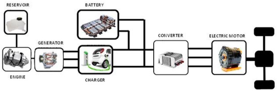
two.3.1. Series Hybrid EVs (SHEV)
The combination of thermal and electric motor in serial is the simplest class of hybrid car (Figure 1). For the vehicles in this category, only the drive is continued to the drive arrangement. The motor is powered either by batteries or by a generator driven past the internal combustion engine. The generator feeds the electrical motor when the traction load increases or charges the batteries when the load is small. Yet, there are certain disadvantages associated with SHEVs: (i) The generator and the motor are now divide parts, which in plough results in increased toll and reduced performance due to the presence of more individual systems [23], (2) The electric motor must exist of loftier power to accommodate a high elevate, such as climbing uphill.
Figure i. Schematic of series hybrid electrical vehicles (SHEV).
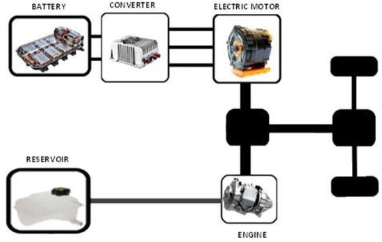
2.3.two. Parallel Hybrid EVs (PHEV)
Parallel layout (Effigy ii) is the near common drive arrangement topology in hybrid vehicles. In this type of vehicle, the internal combustion engine and the motor are directly connected to the drive system. Motility process tin can exist described as follows: during low traction need, the motorcar is driven either by the motor or by the internal combustion engine alone. When only one of the two engines is operating, the other will be disconnected via a clutch. If demand increases then both engines help to drive the vehicle. Most PHEV designs combine the generator and the engine into i unit. PHEV uses smaller batteries than the other hybrids and need a smaller pull motor. The disadvantage of PHEV is its circuitous mechanical systems.
Figure 2. Schematic of parallel hybrid electrical vehicles (PHEV).
2.three.3. Series-Parallel Hybrid EVs (SPHEV)
The SPHEV arrangement is a combination of the 2 above-mentioned devices. In the series-parallel configuration, the internal combustion engine and the motor connected to the transmission system can propel the vehicle either together or separately. The gasoline engine tin help drive the vehicle or charge the batteries through the generator connected to it. It is a solution, though much more than circuitous and expensive. A disadvantage is that SPHEVs require very complex command systems.
2.three.4. Fuel Prison cell Hybrid EVs (FCHEV)
It is a hybrid type of car that looks like a SHEV (serial), except that it uses a fuel jail cell (FC) HEV. A fuel cell is a chemical automobile that generates electricity based on hydrogen and only emits water vapor. The principle of fuel cell performance is the contrary electrolysis process in which hydrogen and oxygen gases are combined to produce electricity with h2o and heat as byproducts. FCHEV technology has only been piloted in few vehicles, due to its high cost (hydrogen product is unprofitable and there are difficulties in transporting and distributing it).
2.3.5. Plug-In Hybrid Electric Vehicles (PHEV)
A PHEV (Figure 3) is a hybrid vehicle in which the batteries tin be recharged either by connecting the vehicle to an external ability source either internally via the motor-driven generator or by braking every bit in standard HEVs. External electricity can come from the power grid, including domestic or autonomous systems or even from renewable free energy sources. PHEVs have a lower electric range compared to typical HEVs per recharge if the bombardment is used only have a larger range in general because the motor-generator motility can assistance the organisation when the batteries are wearied. Moreover, due to the big electric motor, PHEVs have a college braking capacity compared to the traditional HEV. Other benefits of PHEVs include longer distance coverage than HEVs, low operating toll compared to a gasoline vehicle, while they are besides environmentally friendly. The major drawbacks are still high costs and unavailability of fast charging stations.
Figure 3. Structure of a plug-in hybrid electric vehicle.
3. Charging Technology Analysis and Standards
3.one. Charging Modes (IEC-61851-one)
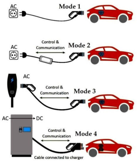
The international electrotechnical commission, under IEC 61851-one, defined four means of charging electric vehicles [24,25,26], co-ordinate to the type of power that the EV receives, the voltage level, the potential existence of a two-manner communication between the car and the charging station, as well as the existence of a grounding and protection device. Charging modes are categorized equally follows:
iii.1.1. AC Mode-1: Domestic Socket and Extension String
Almost all PHEVs are provided by the manufacturer with a unproblematic charging cable. In AC mode-1, the cablevision at 1 end has the standard SAE J1772 socket, attached to the vehicle's charging port. The other end of the cable is a standard socket that tin be continued straight to a wall socket at home. There is no protection confronting electrical stupor on the cable. The only protection is the anti-electrocution installation of the home. AC style-1 charging can be provided to the vehicle with a built-in charger upwardly to 1.9 kW from a single-phase 250 V Air conditioning, or iii-stage 480 5 AC at a frequency of 50–60 Hz. The usual charging time is 10–xv h from a household socket (ten or 16 A). AC way-1 is in general a tedious charging mode, and for this reason information technology is preferred mainly during the night.
3.1.two. AC Way-2: Slow Charge from a General Purpose Socket with an Electrical Daze Protection Device (RCD) on the Cablevision
In this mode, charging is performed from a standard socket, but with an external vehicle supply equipment (EVSE) special cablevision, known as an occasional employ cable or casual utilise cable, it is unremarkably provided with the EV from the manufacturer. This cablevision provides in cable residual current device (RCD), maximum current protection, increased temperature protection, as well as protective earth detection (from wall socket). As with Air conditioning Mode-i, power is received from a single-stage 250 V Ac or 3-phase 480 V AC at 50–60 Hz, merely the current can achieve up to 32 A.
3.ane.3. AC Mode-3: Semi-Fast Charging from a Special Socket
This mode, in general, allows faster loads than mode 1 and ii, depending on the grid connection and the power of the vehicle charger. Moreover, communication is established betwixt the vehicle and the socket via the airplane pilot line.
3.i.4. DC Mode 4: Fast Charging Using an External Charger in DC
DC Way 4 charging normally uses an off-lath charger that has Ac to DC converters. Here, the vehicle is recharged in less than one hour with a DC power supply with a maximum value of upward to 400 A. The external charger is powered by a three-stage circuit at 240, 400, 480, or 575 VAC. The vehicle communicates with the external charger for full charge control and protection against electrical shocks. Rapid charging is useful for quickly restoring the state of accuse (SOC) partially or fully during the twenty-four hours, to complete a trip that is greater than the all-electric range (AER) of the vehicle.
All charging modes are depicted in the Effigy 4 below.
Figure iv. IEC 61851-1 charging modes.
3.2. Charging Levels
The society of automotive engineers (SAE) technical committees has developed a model, namely SAE J1772, which covers the electrical performance requirements for charging EVs/PHEVs [27]. In the post-obit sections, the bones Air conditioning levels are described.
3.2.1. AC LEVEL-1
Ac LEVEL-1 uses a 120 V socket and a maximum current of xvi A. With these values, the maximum charging ability reaches 1.9 KW. Charging is done with a cable type SAE J1772. The charger is built into the car. Notwithstanding, AC Level-1 is accompanied with tiresome charging time. Every hour of accuse with AC LEVEL-one corresponds to 4–v miles driving around.
three.two.2. AC LEVEL-ii
In this case, if the charging is done at abode with a single-stage 240 V network, then the maximum current is about 30 A, and the maximum charging ability is 7.two KW. The charging cable can be the aforementioned every bit Air conditioning LEVEL 1, (SAE J1772). AC LEVEL ii charging is selected for charging at domicile, too equally in public charging facilities powered past three-phase alternating current and offers output power up to xix.2 kW using a born charger. Here, the maximum electric current value tin can achieve 80 A and requires an electrical circuit that supports this higher electric current value. In this case, the charging is washed with a cable that has a type-2 connector MENNEKES (according to IEC-62196). Air conditioning LEVEL 2 is preferred to AC LEVEL 1 for shorter charging times.
The Ac LEVEL-1 and AC LEVEL-2 charging modes apply a charger that is integrated into the EV. The charger's power is proportional to the charge level and supply from the grid (single-phase or 3-phase). For example, a vehicle with a six.6 kW charger requires a 230V/32A supply and its 40 kWh batteries tin can be charged in six to eight hours. Equally a general rule, LEVEL 2 charging will provide approximately 15 miles of travel for one hr of charging on vehicles with a three.three kW charger, or 30 miles of travel, for one 60 minutes of charging for vehicles with a vi.vi kW charger.
3.2.3. Air conditioning LEVEL-3: Semi-Fast Charging from a Special Socket
This is a new charging choice developed by SAE to provide upward to 130 kW power, making the SOC very fast, and using 3-stage alternating electric current at 400 V. To handle the high output power, the LEVEL 3 chargers are much larger in size, and heavier in weight than the LEVEL i and 2 chargers. Moreover, LEVEL 3 chargers require dedicated cooling equipment for loftier-powered electronics power. Equally a result, LEVEL 3 chargers are not installed on the vehicle, simply are externally on a stable basis.
3.2.four. DC LEVELS Fast/Superfast Charging from an External Charger Providing DC Ability
Fast DC charging ordinarily uses an off-board charger to provide Air-conditioning to DC conversion. Here, the vehicle is recharged in less than one hour with a DC power supply with a maximum value of upward to 400 A. The external charger is powered by a three-phase excursion at 240, 400, 480, or 575 VAC. The vehicle communicates with the external charger and the vehicle, for full charge command and protection against electric daze. Fast charging is useful for speedily restoring the SOC partially or fully during the twenty-four hour period, to complete a journeying that is greater than the AER of the vehicle.
4. Wireless Charging Systems
The mutual do for charging electric or hybrid cars is to use a cable to ship electricity from the source. Nonetheless, anterior charging technology eliminates the demand for any cables. Information technology uses an electromagnetic field instead of a cable to transfer energy between the source and the receiver. Wireless-inductive charging is divided into ii categories: static charging where the vehicle is stationary over the charger to first charging its battery, and dynamic charging where the vehicle is charging while driving on the route [28,29].
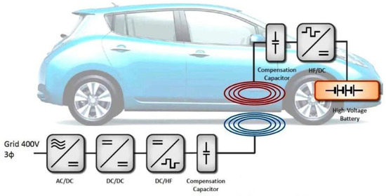
four.1. Static Wireless Electrical Vehicle Charging System (Southward-WEVCS)
The operating principle of an S-WEVCS (Figure 5) is similar to that of the transformers, where energy is transferred from a primary to a secondary ringlet [xxx]. Initially, Air conditioning voltage is converted to DC using an Ac/DC rectifier. Subsequently, a loftier frequency DC/Ac converter provides high frequency current to the primary curlicue, which is installed downwards the road. In this context, the current in the emitting coil creates an alternate magnetic field, which induces an alternate voltage on the receiver coil. The coil of the receiver, or secondary coil, is installed under the front end, rear, or eye of the machine, and its construction is very important to avert significant losses due to improper handling, wearable, and limitation of the identification of foreign objects. To increase the organisation's ability transfer capability, a resonant capacitor is used in the secondary ringlet. Finally, an AC/DC rectifier converts the alternating voltage of the secondary curlicue to continuous and so that the bombardment of the vehicle is charged. S-WEVCS tin replace the charging cable of PEVs with the advantages of simplicity, reliability, user safety (from electric shock), and piece of cake to apply. The wireless ability transfer (WPT) system is activated when the vehicle reaches the charging area. The charging time depends on the source ability level, the charging coil sizes and the air gap distance between the 2 coils. The average altitude between low-cal vehicles is near 150–300 mm. Static WEVCS tin can exist installed in auto parks, parking lots, houses, commercial buildings, shopping centers, and park facilities.
Figure 5. The S-WEVC arrangement.
Still, there are certain problems associated with S-WEVCS. They can exist used only when the car is parked in car parks, or in a garage. Moreover, there is limited ability transfer compared to traditional plug-in chargers. Finally, the WPT (static) wireless power transfer classes can reach 22 kW according to the new J2954 electromagnetic compatibility (EMC) topic.
4.2. Dynamic Wireless Charging Organization for Electric Vehicles (D-WEVCS)
Electric vehicles loaded with cable or South-WEVCS generally confront a major obstacle: the range of travel. To overcome this state of affairs, either frequent charging of the vehicle is required (which means that it should exist parked somewhere, and for some fourth dimension to accuse its batteries) or a larger battery pack should be installed in the vehicle, resulting in actress toll and weight. Dynamic electrical vehicle wireless charging (D-WEVCS) is a engineering science that reduces the issues associated with the range and cost of electric cars. This method charges the batteries, while the vehicle is in motion, and the vehicle'south autonomy is increased.
Nether the floor of the pavement, coils are placed in a row and at a certain distance from i another. These coils are primary coils fed by loftier voltage, high frequency Air conditioning circuits. Like the static WEVCS, the secondary coil is located under the vehicles. When EV passes over the primary coils, it receives a magnetic field through a receiver coil and converts the scroll electric current to DC in order to accuse the batteries. A D-WEVCS faces some issues, such equally the large air gap betwixt the source and the receiver and the alignment with the coils on the road. These ii obstacles mainly affect power transfer efficiency. The average air gap ranges from 150 to 300 mm for small passenger vehicles and increases for larger vehicles. The alignment of the car with the transmitter coils tin be done hands with independent driving. The electronics of the vehicle perceive the divergence from the scroll line and right the class for maximum ability transfer. Overall, installing initial infrastructure for this technology is costly. Dynamic-WEVCS can easily be integrated into many electric applications, such as low-cal vehicles, buses, rail, and transport vehicles [31].
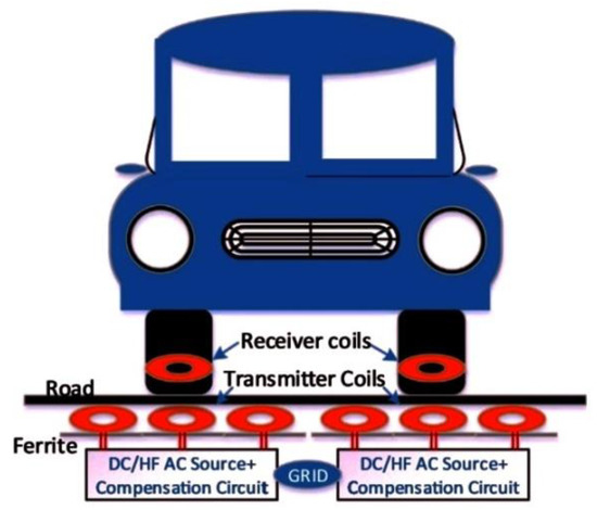
iv.iii. In-Cycle Wireless Charging Systems (IW-WCS)
The air gap between the source and the receiver during wireless charging plays a major office in the performance of the system. The solution comes with the development of the IW-WCS for static and dynamic charging (Figure 6), which means that the vehicle tin be charged while in standby or in motion. Similar other WEVCS, the chief coils are located below the surface of the pavement. Electronic circuits convert the supply current into a 100 kHz high frequency (HF) AC source, which is connected to primary windings. The secondary coils are mounted on the tire structure. Thus, the air gap between source and receiver coils is smaller, compared to electric current static or dynamic WEVCS. The detailed internal positioning of the receiver coils is shown in the effigy to a higher place. The advantages of such an organisation are that only the item receiver curlicue, which comes into contact with the transmitter, is activated [32].
Effigy half dozen. In-wheel wireless charging.
5. V2G Technology
Through bi-directional power transfer, electrical ability is taken from the filigree or produced past photovoltaic panels and used to charge EVs connected to the system. As long as an EV is plugged in, the stored energy of the batteries can exist fed back into the grid, to stabilize it in case of shortage or excess quantity. This is an integrated energy management philosophy, where the ability grid distributes and receives free energy stored in EV batteries via vehicle-to-filigree or V2G applied science and is designed to better manage overall power [33]. Usually nigh cars are parked 90–95% of the time, charging the car in the evening, and ability the filigree, giving energy back, at superlative times. V2G applied science is useful considering of a major weakness in the current power filigree, which is the failure to shop electricity and the use of these stocks to serve hours of increased need. The amount of energy to be given back to the grid depends on the type and dimensions of the electric vehicle. For example, in the case of a battery-powered electric vehicle, the stored free energy depends on the capacity of the batteries, and in the case of fuel cell use, the stored free energy depends on the mass of the fuel (east.1000., compressed hydrogen). Here nosotros have economic benefits, both in terms of the ability filigree and money savings, that would be attributed to higher demand service solutions, too, as on the possessor-operator side of electric vehicles.
Two strategies are provided for loading and unloading V2G PEVs during system failures [34]: In the first strategy, if the charging station (CS) is in the charging country of the car, then the charging of the PEVs stops and the bachelor ability from all the connected vehicles is used to supply ability to the arrangement. In the second strategy, as soon as a failure is detected in the organization, the PEV charging stops. If the available power from vehicles continued to V2G way (programmed belch/V2G) is sufficient to restore energy to the system, PEVs without V2G function are disconnected from the system. If the power from V2G-connected vehicles is not enough, then vehicles simply plugged into the filigree without V2G part are converted to V2G mode to fill the electricity demand gap. An actual implementation of V2G organization is described in [35].
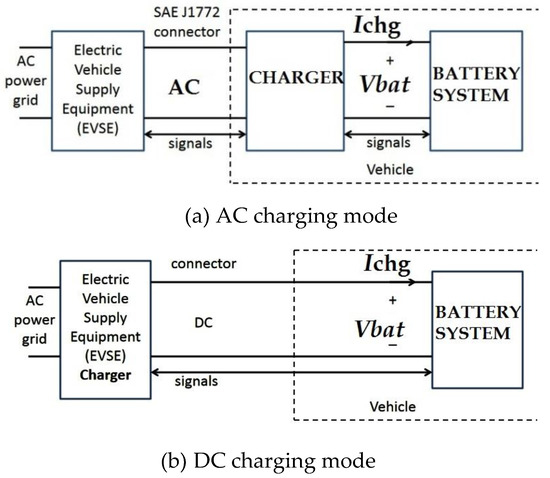
In order for a vehicle to operate in V2G way, there must be ii weather condition. The commencement is to accept electronic power circuits that support V2G technology. The second requirement is to have a real-fourth dimension communication with the network operator for power demand [36]. The device that supplies the electricity from the filigree to the electric vehicle is the EVSE and tin can provide alternate Air conditioning or DC straight current with different power values (Figure 7). If EVSE supplies Air-conditioning ability, there is an Air conditioning ability flow betwixt the vehicle and the EVSE. Therefore, the vehicle has a built-in inverter to catechumen the Ac to DC needed to accuse the batteries. If EVSE provides DC power to the DC vehicle, then the DC opposite current menstruation is DC. In this case, the inverter is included in the off-lath EVSE. The BMS (battery management organisation) assumes full charge control and battery belch in V2G mode. More specifically, the BMS monitors the SOC (land of accuse) of the battery or cells and adjusts the power level of the inverter.
Figure 7. Diagram of electric vehicle bombardment charger.
During V2G operation, EVSE communicates with the network operator exchanging data on power demand. If the network requests ability from the vehicle, it sends a request to EVSE. EVSE volition then contact the BMS from which it volition request validity. The BMS responds and controls the inverter to start the power flow. This happens when AC LEVEL is charged. For DC LEVEL charging, the current exchanged by the vehicle is DC. The inverter is mounted in the EVSE. In this case, the BMS controls the bombardment output. An of import factor for battery longevity is the design of the BMS. If the charging and discharge is properly controlled, so the bombardment life is longer [37].
6. Energy Direction
There are four locations where vehicle owners will be able to accuse their vehicles: in their ain home, at their place of service, at the fleet's fleet, or at commercial charging stations [38].
6.1. Charging at Home
Hither we have vehicle to dwelling (V2H), which can be considered as a preliminary step for the V2G. Vehicle owners can use their cars every bit a source of energy for the household and save coin on the electricity beak or provide backup ability during power outages or fill-in power. Most abode loads are achieved through Air conditioning level ii charging due to lower charging times compared to Ac LEVEL 1. There is also the option to accuse DC LEVEL ane with the appropriate EVSE. Note that if charging is done overnight, this available time is enough to restore battery ability. As far as the AC LEVEL 3 load is concerned, information technology adds excessive load to the firm's electrical installation, and is not practical at all for single-family homes, considering it requires upgrading the electrical installation, which is costly.
6.two. Charging at Work
Here we take the pick of re-charging out of residence with the vehicle to building (V2B) script. An enterprise may have parking facilities for its customers, or staff, where recharging of EVs tin take place. In this scenario, the company installs stations, from which many of them are combined with solar covers in order to achieve a meliorate load management. Vehicles arriving at the workplace are immediately connected to fully recharge earlier the region'due south demand is maximized. Charging tin be at AC LEVEL 2 or Air conditioning LEVEL 3. The choice of the accuse level depends on the nature of the space, and the requirements of the vehicles parked. With the vehicles continued to the stations, we have a meaning amount of stored energy that can be used equally a ability supply for an office building in club to reduce costs or provide critical backup power for high availability business operations, such as data centers. Hοwever, a major drawback is that businesses have limited working hours. Thus, batteries may not exist fully recharged sometimes, and the available vehicle power for home travel volition non be enough.
half-dozen.three. Charging Fleet of Vehicles
Vehicle fleet charging has a common point with workload, as it appears in the working environment. The deviation, however, is that CSs used here are for the cars belonging to the company. A concern owner may ain a significant number of EVs, and be connected to charging during the solar day and working hours that coincide with peak demand hours. But there is a possibility that these parked vehicles will be bachelor for V2G services at the time the business does not work. Some types of EV fleets may have greater advantages in V2G technology than others. An example is a fleet of electric school buses. The buses take large chapters batteries and usually operate at specific times and days during the week, and so remain parked for known durations (one night and weekends). Therefore, a large amount of stored energy can exist quickly disposed of during off-vehicle hours. Equally far as the loading levels are concerned, it is as well the case in the workplace.
six.four. Commercial Accuse
Hither we are talking about CSs, which may be in public places such as motorways, airports, harbors, railroad train stations, simply also in businesses such as restaurants, theaters, entertainment centers, and doctors' or lawyers' offices for profit. Charge levels may vary. A station at a port or airport can be charged with Ac LEVEL two or DC LEVEL 1, and the reason is that the vehicle users travel and exit the vehicles for a long time parked, without excluding the remaining levels of charge. Nevertheless, at airports and ports we may take short-term parking areas with a need for fast charging. The charging requirements are Air conditioning LEVEL iii and DC LEVEL 2. Other short-term spaces, such as fast food restaurants, cafes, section stores, and gas stations, likewise have the same charging requirements. CSs can exist installed along motorways between big and remote cities. This enables a PEV to travel betwixt areas where the distance is greater than the distance the vehicle tin travel when fully charged.
six.5. Types of Charging Stations
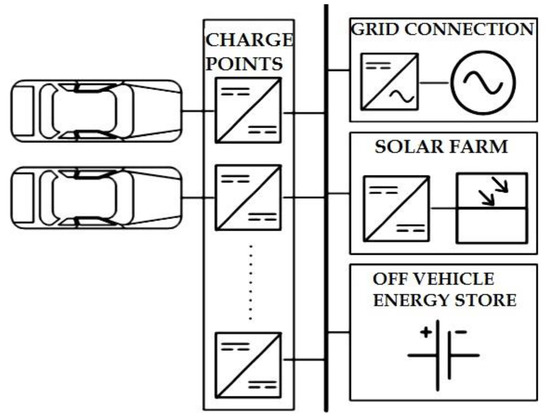
CS defines the charging infrastructure for the electric vehicle consisting of one or more charging points (CP) (Figure 8) and their connection to the distribution network [39,40]. CSs can exist categorized into 2 types: fixed charging station (FCS) and mobile charging station (MCS). FCS is a stock-still installation with multiple charging points. Power is obtained directly from the main voltage through a transformer. Additional equipment that a station may include are generators, battery packs, or PV cells to ensure reliable EV charging. Given the ever-increasing number of EVs, information technology is essential to effectively programme the capacity and schedule the power supply for the EV charging stations. In [41], a holistic framework has been adult for the planning and operation of an EV charging station, taking into consideration the supply of both the filigree and local renewable energy. A review on system planning of grid-connected EV CSs and key technologies tin can exist found in [42]. Diverse charging methodologies are farther analyzed in [43].
Figure 8. Block schematic of EV charging station.
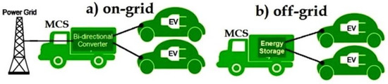
The MCS is an electrical or hybrid vehicle equipped with a small number of CPs and with some type of energy storage such every bit ultracapacitors. MCS units avert some challenges associated with EV charging infrastructure. They avoid the demand for designated EV parking spaces (and enforcement tools to preclude non-EV users from parking at that place), can disconnect as soon every bit charging is complete (allowing EV drivers to depart at will instead of on a set schedule), require less investment upfront investment (no trenching or permitting), and can exist repositioned or sold if utilization is low [44].
MCS's main power source is the network. The MCS tin can park to a FCS with which it is connected and can charge the nearest EV. This charging role of the MCS is called "on-filigree" because it charges the nearby EV using its connection to the power grid. MCS can also park to some FCS to charge energy storage. The advantage of MCS is to travel some distance, and park and charge an EV outside FCS using the stored free energy. In this instance, we have an off-grid charging function. Both modes are depicted in Figure ix.
Figure ix. Mobile charging station. (a) on-filigree charging mode; (b) off-grid charging mode
Co-ordinate to [45], where the operation of FSC and MCS networks is analyzed, the MCS network has improve waiting time performance than the FCS network. The advantage of the MCS network over the FCS network becomes very significant when the arrivals of EVs are large. Outage probability and service waiting delay performances of MCSs are besides examined in [46], where significant improvements are outlined. An alternate approach is proposed in [47], where EVs can also act equally mobile energy storage (MES) units. In this context, CSs inform the grid on their charging capabilities and EVs on their planned travel routes. In the case of a limited-capacity CS, the filigree examines if a scheduled route is nearly to take place in due time, including the aforementioned CS and a resourceful CS. If this is true, and so energy can be transferred via MESs. As was shown in [47], the proposed scheme can be applied by the local power organisation operator (PSO) to balance the system energy without excessive power infrastructure upgrade, while MESs are stimulated to fulfill tasks in a toll-efficient way.
7. Democratic Vehicles
An democratic vehicle (AV) is defined every bit whatever type of vehicle where all mechanical-related procedures (i.e., motion, dispatch, etc.) can be performed with limited or no human interaction (Effigy x). In this context, two main classifications can be found in literature regarding AVs ([48]): a. semi-autonomous, and b. fully autonomous. In the first case, semi-autonomous cars tin accelerate, brake and steer, keep the distance from the car in front, and likewise go on the lane at speeds up to 130 km/h, but the driver is still required and is still in total command.
Effigy ten. Autonomous vehicle in city driving.
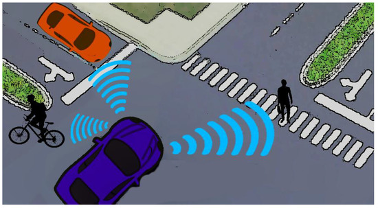
Nowadays, autonomous driving of smart vehicles has attracted scientific interest, as apart from wireless networks evolution, the concept of electric smart grids is shifting towards standardization and development. In addition to the advances in computing and perception hardware, this rapid progress has been enabled by major theoretical progress in the computational aspects of mobile robot move planning and feedback control theory [49,50]. In this context, independent vehicles can perform various operations, such as commitment to individuals on demand, especially to elderberry people. Τherefore, the establishment of a reliable wireless link is of primary importance, as the vehicle needs to constantly receive information on road traffic and update scheduled tasks, receive on demand new orders, and finally be informed on power charging stations. By providing the vehicle with real time maps for navigation, speed warnings, road hazards, vulnerabilities, heads upward display systems, sensor data sharing, etc., advanced driver assistance features will reduce fatal accidents and traffic congestion. These features volition enable the vehicle to dynamically change its course on the road nether certain scenarios and atmospheric condition. The and then-called vehicle to network (V2N) communications are necessary for this use case, including brusque range modeling and recognition of surrounding objects and vehicles plus mid to long range modeling of the surroundings, with upward-to-engagement information on the latest digital maps, traffic signs, traffic signal locations, road structure, and traffic congestion.
For autonomous driving engineering to be unlocked, many experts agree that large-scale adoption of 5G—the adjacent-generation wireless engineering—is required [51,52], as 5G tin can run over existing infrastructure, though cellular stations upgrades are needed. Moreover, 5G could be one unifying connectivity standard engineering science that could avoid market and technical fragmentation and which could lower the cost for automotive manufacturers. Co-ordinate to scientific studies, 5G technology can as well offer evolved prevention capabilities. In disquisitional scenarios, such as car accidents, the detection and control system of an AV must have fast reaction times. Under this status, a set of sensor technologies, for case, can achieve immediate communication with other autonomous cars, radar, lasers, sonar devices, and cameras [53,54,55]. In current state, available LTE (4G) supports data manual at 100 Mbps. On the other side, speed in 5G networks can reach upwards to 5Gbps. In that point of view, the deployment of 5G networks over the next decade is going to boost the development of AVs and increase corresponding safety.
eight. Conclusions
The evolution of electrification with a view to exploiting renewable energy sources has begun. The final goal is the full interconnection of EVs to SEGs. This transition from one state to the other, i.due east., the utilize of conventional vehicles at one finish, and power-operated at the other, past exchanging electricity with the power grid, certainly cannot take place without intermediate steps. These steps mainly include HEVs, which can demonstrate the benefits of this new engineering science to consumers, and thus drive them smoothly to the prevalence of electric drive. The transition to electrification and V2G engineering science requires investment in this sector and boosted costs, which can easily be compensated in the short or long term. In the outset case, the compensation is related to the direct economical benefits to the owner of the EV, and to the V2G network operator from the savings in the consumption of electricity. Yet, bounty is also related indirectly to the burden on the state budget to tackle the burden on the contagion of the surroundings by the use of not-renewable energy sources.
Moreover, technological developments in other related sectors (i.e., wireless communications as the era of 5G networks is budgeted) can heave scientific advances in EV technology. AV concept offers beneficial energy usage and environmental advantages, and it may influence future globe perspectives in various fields: traffic reduction, vehicle and driving rubber, travel behavior, fuel efficiency, road crash prevention, and parking benefits.
Author Contributions
Conceptualization, T.A.South. and P.K.G.; methodology, T.A.Due south., P.K.Thousand., and C.N.I.; investigation, P.T.T., E.G.T., and T.V.Z.; writing—original typhoon preparation, T.A.Due south., P.K.G., C.N.I., P.T.T., East.Thousand.T., and T.5.Z.; writing—review and editing, T.A.South., P.Chiliad.G., C.N.I., P.T.T., Due east.G.T., and T.5.Z. All authors have read and agreed to the published version of the manuscript.
Funding
This research received no external funding.
Conflicts of Interest
The authors declare no disharmonize of interest.
References
- Sthel, M.S.; Tostes, J.G.R.; Tavares, J.R. Current energy crisis and its economic and ecology consequences: Intense human cooperation.Nat. Sci.2013,5, 244–252. [Google Scholar] [CrossRef]
- Yong, J.Y.; Ramachandaramurthy, V.G.; Tan, K.G.; Mithulananthan, N. A review on the state-of-the-art technologies of electrical vehicle, its impacts and prospects.Renew. Sustain. Free energy Rev.2015,49, 365–385. [Google Scholar] [CrossRef]
- Du, J.; Ouyang, M. Review of electrical vehicle technologies progress and development prospect in China.Earth Electr. Veh. J.2013,6, 1086–1093. [Google Scholar] [CrossRef]
- Un-Noor, F.; Padmanaban, South.; Mihet-Popa, L.; Mollah, M.N.; Hossain, East. A Comprehensive study of key electric vehicle (EV) components, technologies, challenges, impacts, and future direction of development.Energies2017,10, 1217. [Google Scholar] [CrossRef]
- Lopes, J.A.; Soares, F.; Almeida, P. Integration of Electric Vehicles in the Electrical Power System.Proc. IEEE2011,99, 168–183. [Google Scholar] [CrossRef]
- Monteiro, V.; Afonso, J.A.; Ferreira, J.C.; Afonso, J.L. Vehicle electrification: New challenges and opportunities for smart grids.Energies2018,12, 118. [Google Scholar] [CrossRef]
- Chau, M.T.; Jiang, C.; Han, W.; Lee, C.H.T. State-of-the-art electromagnetics research in electric and hybrid vehicles.Prog. Electromagn. Res.2017,159, 139–157. [Google Scholar] [CrossRef]
- Singh, K.V.; Bansal, H.O.; Singh, D. A comprehensive review on hybrid electric vehicles: Architectures and components.J. Modernistic. Transp.2019,27, 77–107. [Google Scholar] [CrossRef]
- Mwasilu, F.; Justo, J.J.; Kim, East.-Chiliad.; Do, T.K.; Jung, J.-W. Electric vehicles and smart grid interaction: A review on vehicle to grid and renewable energy sources integration.Renew. Sustain. Energy Rev.2014,34, 501–516. [Google Scholar] [CrossRef]
- Uddin, Grand.; Dubarry, M.; Glick, One thousand.B. The viability of vehicle-to-filigree operations from a battery technology and policy perspective.Free energy Policy2018,113, 342–347. [Google Scholar] [CrossRef]
- White, C.D.; Zhang, M.1000. Using vehicle-to-filigree engineering science for frequency regulation and peak-load reduction.J. Power Sources2011,196, 3972–3980. [Google Scholar] [CrossRef]
- Krueger, H.; Cruden, A. Modular strategy for aggregator control and data exchange in large scale Vehicle-to-Grid (V2G) applications.Energy Procedia2018,151, 7–xi. [Google Scholar] [CrossRef]
- Yimin Zhou, Y.; Li, 10. Vehicle to Filigree Technology: A Review. In Proceedings of the 2015 34th Chinese Control Conference, Hangzhou, Prc, 28–30 July 2015. [Google Scholar]
- Daim, T.U.; Wang, X.; Cowan, K.; Shott, T. Technology roadmap for smart electrical vehicle-to-grid (V2G) of residential chargers.J. Innov. Entrep.2016,5. [Google Scholar] [CrossRef]
- Krainyukov, A.; Krivchenkov, A.; Saltanovs, R. Performance assay of wireless communications for V2G applications using WPT engineering in energy transfer.Procedia Eng.2017,178, 172–181. [Google Scholar] [CrossRef]
- Fabio Arena, F.; Pau, G. An overview of vehicular communications.Time to come Internet2019,11, 27. [Google Scholar] [CrossRef]
- Tao, M.; Ota, K.; Dong, M. Foud: Integrating fog and cloud for 5G-enabled V2G networks.IEEE Netw.2017,31, viii–13. [Google Scholar] [CrossRef]
- Li, Y.; Yu, Thousand.; Liu, J.; Deng, F. Design of V2G auxiliary service system based on 5G technology. In Proceedings of the 2017 IEEE Conference on Energy Net and Energy System Integration (EI2), Beijing, China, 26–28 Nov 2017. [Google Scholar]
- Zong, Due west.; Zhang, C.; Wang, Z.; Zhu, J.; Chen, Q. Compages design and implementation of an autonomous vehicle.IEEE Admission2018,6, 21956–21970. [Google Scholar] [CrossRef]
- Chan, C.C.; Bouscayrol, A.; Chen, K. Electric, Hybrid, and Fuel-Cell Vehicles: Architectures and Modeling.IEEE Trans. Veh. Technol.2010,59, 589–598. [Google Scholar] [CrossRef]
- Donateo, T.Hybrid Electrical Vehicles; InTech Publications: London, UK, 2017. [Google Scholar]
- Vidyanandan, K.V. Overview of Electric and Hybrid Vehicles.Free energy Scan2018,3, vii–14. [Google Scholar]
- Propfe, B.; Redelbach, M.; Santini, D.J.; Friedrich, H. Cost analysis of plug-in hybrid electrical vehicles including maintenance & repair costs and resale values. In Proceedings of the EVS26 International Battery, Hybrid and Fuel Cell Electric Vehicle Symposium, Los Angeles, CA, United states of america, 6–nine May 2012; pp. 886–895. [Google Scholar]
- Falvo, Μ.C.; Sbordone, D.; Bayram, I.S.; Devetsikiotis, Thousand. EV Charging stations and modes: International standards. In Proceedings of the International Symposium on Power Electronics, Electrical Drives, Automation and Movement, Ischia, Italy, xviii–xx June 2014. [Google Scholar]
- Botsford, C.; Szczepanek, A. Fast charging vs. slow charging: Pros and cons for the new historic period of electric vehicles. In Proceedings of the International Battery, Hybrid and Fuel Cell Electric Vehicle Symposium, Stavanger, Norway, 13–16 May 2009. [Google Scholar]
- Kong, P.-Y.; Karagiannidis, Thousand. Charging schemes for plug-in hybrid electric vehicles in smart grid: A survey.IEEE Access2016,4, 6846–6875. [Google Scholar] [CrossRef]
- SAE International. Bachelor online: https://www.sae.org/ (accessed on 22 Dec 2019).
- Panchal, C.; Stegen, S.; Lu, J. Review of static and dynamic wireless electric vehicle charging organization.Eng. Sci. Technol. Int. J.2018,21, 922–937. [Google Scholar] [CrossRef]
- Qiu, C.; Chau, K.T.; Liu, C.; Chan, C.C. Overview of wireless power transfer for electric vehicle charging. In Proceedings of the Globe Electric Vehicle Symposium and Exhibition (EVS27), Barcelona, Spain, 17–20 November 2013. [Google Scholar]
- Magudeswaran, P.; Pradheeba, G.; Priyadharshini, Southward.; Flora, G.S. Dynamic wireless electric vehicle chargins system.Int. Res. J. Eng. Technol.2019,6, 6609–6615. [Google Scholar]
- Mazharov, North.D.; Hristov, S.M.; Dichev, D.A.; Zhelezarov, I.S. Some problems of dynamic contactless charging of electric vehicles.Acta Polytech. Hung.2017,14, 7–26. [Google Scholar]
- Panchal, C.; Lu, J.; Stegen, Southward. Static in-bicycle wireless charging systems for electric vehicles.Int. J. Sci. Technol. Res.2017,6, 280–284. [Google Scholar]
- Kruegera, H.; Crudena, A. Modular strategy for aggregator control and data exchange in large calibration Vehicle-to-Filigree (V2G) applications. In Proceedings of the 3rd Annual Conference in Energy Storage and Its Applications, 3rd CDT-ESA-AC, Sheffield, UK, eleven–12 September 2018. [Google Scholar]
- Galiveeti, H.R.; Goswami, A.Yard.; Choudhury, North.B.D. Bear upon of plug-in electric vehicles and distributed generation on reliability of distribution systems.Int. J. Eng. Sci. Technol.2018. [Google Scholar] [CrossRef]
- Atmaja, T.W.; Susanti, 5.; Mirdanies, K.; Muharam, A. V2G development on public vertical parking lot to support community energy management system.MATEC Web Conf.2018,164. [Google Scholar] [CrossRef]
- Dongqi Liu, D.; Zhong, Q.-C.; Wang, Y.; Liu, One thousand. Modeling and control of a V2G charging station based on the synchronverter technology.CSEE J. Power Free energy Syst.2015,1. [Google Scholar] [CrossRef]
- Ryan Collin, R.; Miao, Y.; Yokochi, A.; Enjeti, P.; Jouanne, A. Advanced electrical vehicle fast-charging technologies.Energies2019,12, 1839. [Google Scholar] [CrossRef]
- Mao, Τ.; Zhang, X.; Zhou, B. Modeling and solving method for supporting 'Vehicle-to-Anything' EV charging mode.Appl. Sci.2018,viii, 1048. [Google Scholar] [CrossRef]
- Atmajaa, T.D.; Mirdanies, Grand. Electrical vehicle mobile charging station dispatch algorithm. In Proceedings of the 2nd International Conference on Sustainable Energy Engineering and Application, ICSEEA 2014, Bandung, Indonesia, 14–sixteen Oct 2014. [Google Scholar]
- Chung, C.-Y.; Chynoweth, J.; Qiu, C.; Chu, C.-C.; Gadh, R. Design of fast response smart electric vehicle charging infrastructure. In Proceedings of the Green Energy and Systems Briefing, Long Beach, CA, USA, 25 November 2013. [Google Scholar]
- Wang, H.; Balasubramani, A.; Ye, Z. Optimal planning of renewable generations for electric vehicle charging station. In Proceedings of the International Conference on Computing, Networking and Communications (ICNC) 2018, Maui, Hello, U.s., 5–8 March 2018. [Google Scholar]
- Ma, C.-T. Organisation planning of grid-continued electric vehicle charging stations and key technologies: A review.Energies2019,12, 4201. [Google Scholar] [CrossRef]
- Saldaña, G.; Martin, J.I.C.; Zamora, I.; Asensio, F.J.; Oñederra, O. Electric vehicle into the grid: Charging methodologies aimed at providing ancillary services because bombardment deposition.Energies2019,12, 2443. [Google Scholar] [CrossRef]
- Hove, A.; Sandalow, D. Electric Vehicle Charging in China and the United States. Columbia, Schoolhouse of International and Public Affairs, Center on Global Energy Policy. Available online: https://energypolicy.columbia.edu/sites/default/files/file-uploads/EV_ChargingChina-CGEP_Report_Final.pdf) (accessed on 22 Dec 2019).
- Yang, S.-Northward.; Wang, H.Due west.; Gan, C.H.; Lin, Y.B. Mobile charging station service in smart grid networks. In Proceedings of the IEEE Smart Grid Communications 2012 Symposium-Smart Grid Services and Management Models, Tainan City, Taiwan, 5–8 November 2012. [Google Scholar]
- Li, Z.; Sahinoglu, Z.; Tao, Z.; Teo, Thousand.H. Electrical vehicles network with nomadic portable charging stations. In Proceedings of the IEEE 72nd Vehicular Technology Conference Fall (VTC 2010-Fall), Ottawa, ON, Canada, 6–9 September 2010. [Google Scholar]
- Chen, N.; Li, Thousand.; Wang, M.; Ma, J.; Shen, Ten. Compensation of charging station overload via on-road mobile energy storage scheduling. In Proceedings of the 2019 IEEE Global Communications Conference (Globecom), Waikola, Hullo, USA, 9–13 December 2019. [Google Scholar]
- Krasniqi, 10.; Hajrizi, E. Use of IoT applied science to drive the automotive manufacture from connected to total autonomous vehicles.IFAC Pap. Online2016,49, 269–274. [Google Scholar] [CrossRef]
- Brian Paden, B.; ˇCáp, M.; Yong, Southward.Z.; Yershov, D.; Frazzoli, E. A survey of motion planning and control techniques for self-driving urban vehicles.IEEE Trans. Intell. Veh.2016,ane, 33–55. [Google Scholar] [CrossRef]
- González, D.; Pérez, J.; Milanés, Five.; Nashashibi, F. A review of motility planning techniques for automated vehicles.IEEE Trans. Intell. Transp. Syst.2016,17, 1135–1145. [Google Scholar] [CrossRef]
- Lema, Yard.A.; Laya, A.; Mahmoodi, T.; Cuevas, M.; Sachs, J.; Markendahl, J.; Dohler, M. Business example and technology analysis for 5G low latency applications.IEEE Access2017,5, 5917–5935. [Google Scholar] [CrossRef]
- Alberio, M.; Parladori, M. Innovation in automotive: A challenge for 5G and across network. In Proceedings of the 2017 International Conference of Electrical and Electronic Technologies for Automotive, Torino, Italy, 15–xvi June 2017. [Google Scholar]
- Heiko, G.S.; Xiaolong, H. Autonomous Driving in the iCity-Hard disk drive Maps equally a Key Challenge of the Automotive Industry.Engineering2016,2, 159–162. [Google Scholar]
- Simsek, M.; Aijaz, A.; Dohler, M.; Sachs, J.; Fettweis, Yard. 5G-Enabled Tactile Internet.IEEE J. Sel. Areas Commun.2016,34, 460–473. [Google Scholar] [CrossRef]
- Campolo, C.; Molinaro, A.; Iera, A.; Menichella, F. 5G Network Slicing for Vehicle-to-Everything Services.IEEE Wirel. Commun.2017,24, 38–45. [Google Scholar] [CrossRef]
This article was originally published by Licensee MDPI, Basel, Switzerland, on December 23, 2019, and has been republished in accordance with the Creative Commons Attribution-NonCommercial-NoDerivatives four.0 International Public License. Yous can read the original article here . The views expressed in this article are those of the author lone and not the WorldRef.
Explore WorldRef services to learn how we are making your global expansion easier and economic!
Thermal Power and Cogeneration | Mining and Minerals | Air Pollution Control | Fabric Handling Systems | Water and Waste material Water Treatment | Spares, Tools and Consumables | Power Plant Solutions | Renewable Power Solutions with Financing
Source: https://worldref.co/w-insights/electric-vehicles-current-state-art-challenges-and-perspectives/
0 Response to "C Chan Proceedings of Ieee the State of the Art of Electric Hybrid and Fuel Cell Vehicles"
Enregistrer un commentaire